Brief introduction to the wheel set
The wheel set have undergone four major versions. The first version is using the suspension system on the driving part of the wheel set. This is because by using this watt linkage version, the heading part of the set can be linked to the frame of the chassis more solidly. Additionally, this can also reduce the mass weight under the spring, which can also improve the high speed performance of the robot. During the design of the watt linkage, I have taken mechanical simulation that when the rods are 60mm in length, the wheel in the midterm of the second rod can reach 42.7117mm on the y axis when the movement on the x axis is less than ±0.1mm. So this design can leave the suspension suspension system enough length to press the spring while keep the positioning of the wheel sets stable. The material of the rods are FR4 fiberglass panel, which is relatively cheaper in comparison to carbon fiber panel, while maintaining enough stiffness.
The second version was designed to maintain the robustness of the robot in the competition. During the test, the shafting design on the rods, with plug-in pots used as axles broke frequently under pressure tests. Additionally, since the driving part of the wheel set is somehow working as cantilever beams, the design of the first version may well separate under high impact. So in this version, the watt linkage was canceled, and two copper column to enhance stiffness. The thickness and the diameter of the wheel is the same as the first version, which is 20mm in width and 130mm in diameter. With an over-molding hardness of 90A and a thickness of 7.5mm, the robot can achieve fluent movement on asphalt, mastic and tile floors.
The first two versions of the wheels are finished in 2023 season. After the test of the season, the cons of these design can be summarized as these 4 points. Firstly, the wheel sets are overweight. The two versions share a mass weight of about 2.2kg, which cause the overall weight of the robot reach 25kg, furthermore causing the acceleration of the robot about 15% less than that of other universities’. Secondly, the torque of the M3508 P19 motor is too much for this working condition. Though a bigger torque of the driving motor can enable the acceleration from static state quicker, the maximum speed of the robot was somehow limited. Thirdly, since the total length of the M3508 motor reach 98.4mm, the rotational radius of the wheel set reach 71mm, which is about 12.5mm bigger than the wheel radius. Finally, there are no hub motors available which both fit the need of volume, weight and torque.
So in summer 2023, I redesigned the wheel set to the third version. In this progress, the goal of design is focused on the integration of parts and the simplify of the design. In this version, expansion sleeve is used to take the place of D-shaped coupling, and metal right-angle adapter are used to enhance the stiffness of the diving part. Furthermore, the number of bearings have been reduced from 3 sets to 2, and later on 1 set. This can also help reduce the processing accuracy requirements of the computer numerical control(CNC) parts. Together with the integration of the rim, side plate and the expansion sleeve fixing CNC parts, this redesigning managed both the simplification of the wheel set and reducing cost. For the hardness of over-molding, since the thickness of over-molding have been reduced to 5mm, the hardness have also been changed to 60A to ensure enough traction. For the overweight problem, this version have achieved 45.5% weight reduction, and have a mass weight of 1.261kg.
The final version of the wheel consider only using the driving part of the motor. To further simplifying the design and ensure that under designed working conditions the motor can be working in a more sufficient state, this version chose to integrate the main body of the driving part of the wheel, and using the gearbox to cancel the design of coupling. In other words, I tried to design a hub motor. For the driving part, since the original motor is GM6020 hollow motor with a status torque of 1.2Nm and there seems to have a matched torque between that and that needed, the gear-ring gearbox’s ratio is 1:7. So the torque is 1.105Nm, and this design can leave enough space for the magnetic encoder and slip ring. The PCB design, serving as the magnetic encoder and the wheel distribution board, have rubber shock-absorption gaskets to ensure that under working conditions the two board will not separate and cause oscillation. Since the motor on this version is carried on a 3mm thick VMA board, the distance between boards is 7mm, leaving enough space for the gaskets and plug bolts. Along with the two double slot board-to-board connectors, the two PCB have five joints to keep stable and aligned.
Images of the design
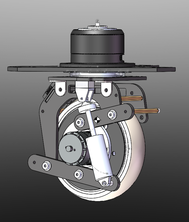
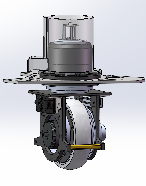
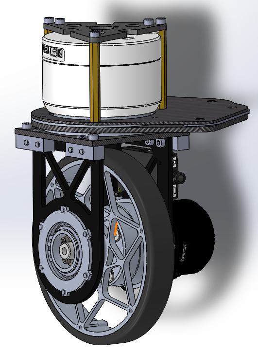
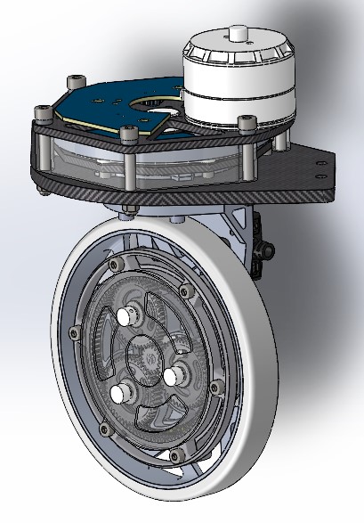
The image of the design of the 4 versions of the synchro-drive wheel sets, v1 ~ v4 respectively.
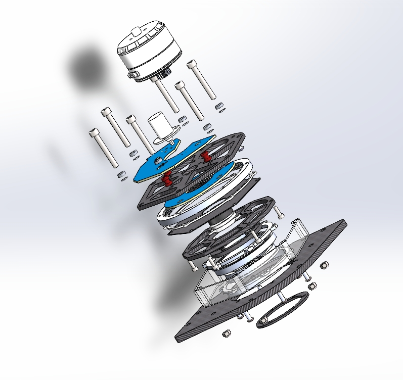
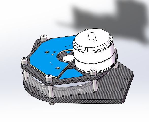
The exploded view and the design of the heading part of the version 4 of the synchro-drive wheel set.