Brief introduction of the project
The project consist of 4 parts: Mechanical design, PCB design, controlling and visual recognition.
For the mechanical design, the robot is consisted of two main parts, the chassis part and the gimbal part. The chassis part have four synchro-drive wheel sets and one timing belt driving the first yaw axis of the gimbal. The synchro-drive wheel sets can enable the chassis to achieve omnidirectional movement. To ensure that the robot can manage to operate in more complex conditions, the gimbal part have 5 DoFs, which are yaw-pitch-pitch-roll-yaw respectively. The mechanical design also have the gearbox and wheel set design, which is shown in detail in the related passages.
The PCB in the project serve as the magnetic encoder and distribution board for the heading part of the wheel set.The PCB have two parts. The upper board have the function to turn the high voltage from the chassis main distribution board to the low voltage needed by the M3508 motor on the heading part and driving part of the wheel set, and the ability to pass position information and can bus messages provided by the hall elements from the downwards PCB board. The downwards board have a chip and four hall elements to work with the magnet ring which rotate with the driving part of the wheel set to provide the heading angle information.
For the control part, I made the kinematic solving of the omnidirectional chassis and made the frame of controlling on the RoboMaster C board (STM32F407IGHx) by using STM32CubeMX. Due to the limit of time, only additional can block and PID block are added. For the gimbal control, the kinematic and inverse kinematic solving of the position of the robotic arm.
I applied the open source YOLO v7 to ensure that the robot have the ability to recognize the context.
Detailed information is shown in the report.
Images of the design
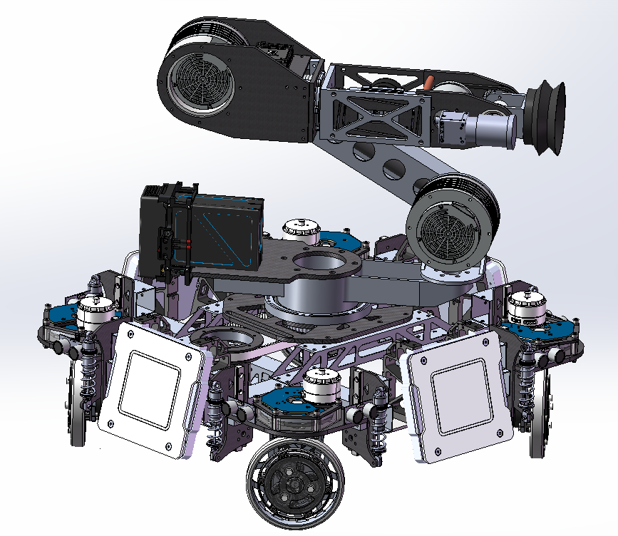
The overview of the design of the robot in this project
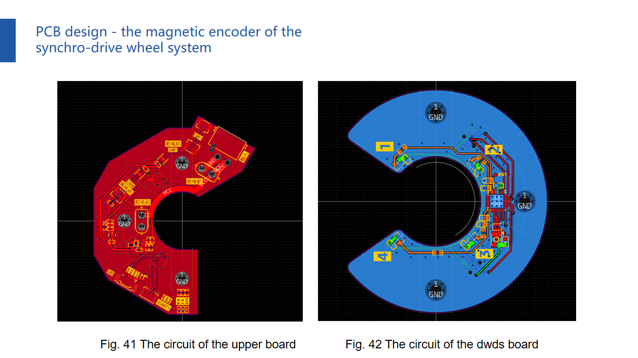
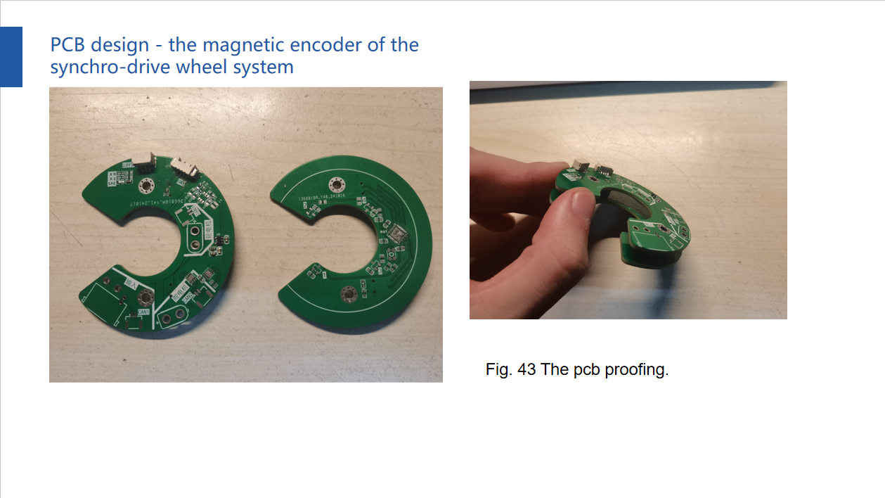
The PPT for the PCB design and the proofing of the PCB.